More photo documentation of the conversion of a Miata to a MiataV8.
The following pics are of a Miata rear subframe modified to accept an 8.8 IRS as found on '90's Thunderbirds and Lincoln MKVIII, as well as some early Mustang Cobras.


The rear mount is more 1/4" strap made into angles to work with the same Energy Suspension part number 4.1126 mounts as the front. It's important to note that the rubber mounts and the steel tubing that runs thru them are designed to fit on the 1/2" thick mounting "ears" at the front of the differential, so using a different thickness material as shown means the length of the tube and the protrusions on the rubber mounts must be shortened accordingly to ensure the proper clamping load. Any looseness at this point would be disastrous. The subframe crosspiece has a "nut bar" made of 3/8" thick stock welded to the crossmember with gussets similar to front. The gussets were cleaned and shiny bright before welding.


Knowing I would be making more conversions, I made a simple wooden fixture to hang the diff in space while building the mounts.
Critical dimensions are: Height of side support centerlines = 6.5", pinion support centerline = 8.0" as measured from the surface of the baseplate. The subframe is mounted on 1.5" blocks to allow clearance for the original axle mounts, which are left in place for the additional bracing.
The diff is positioned so that the stub axle centers are the same as the original Miata axle centers, which locates the diff height and front to back position. These centers were determined by hanging the Miata rear end in place on the subframe in place on the baseplate.
The body of the 8.8 diff is centered side to side with reference to the machined bosses surrounding the axle stub holes and positioned so the pinion flange is perpendicular to the mounting plane of the subframe.
The subframe has six mounting holes, one of the front holes is the primary locator, very close to 12mm clearance, the other front hole is nominally 12mm, but oval, the rest are very generously clearanced, so I didn't try to locate from them other than to draw a rectangle using the centers of the 4 corner holes which became the reference for determining alignment.
It's harder to describe than it is to execute, since the thing is hanging in space, but my thinking is that it's easier to measure and lay out a simple fixture than it is to do a makeshift blocking and shimming of the irregularly shaped diff. I've since moved on to a metal version, the new 8.8 as found on Explorers has different mounts that drove that decision.


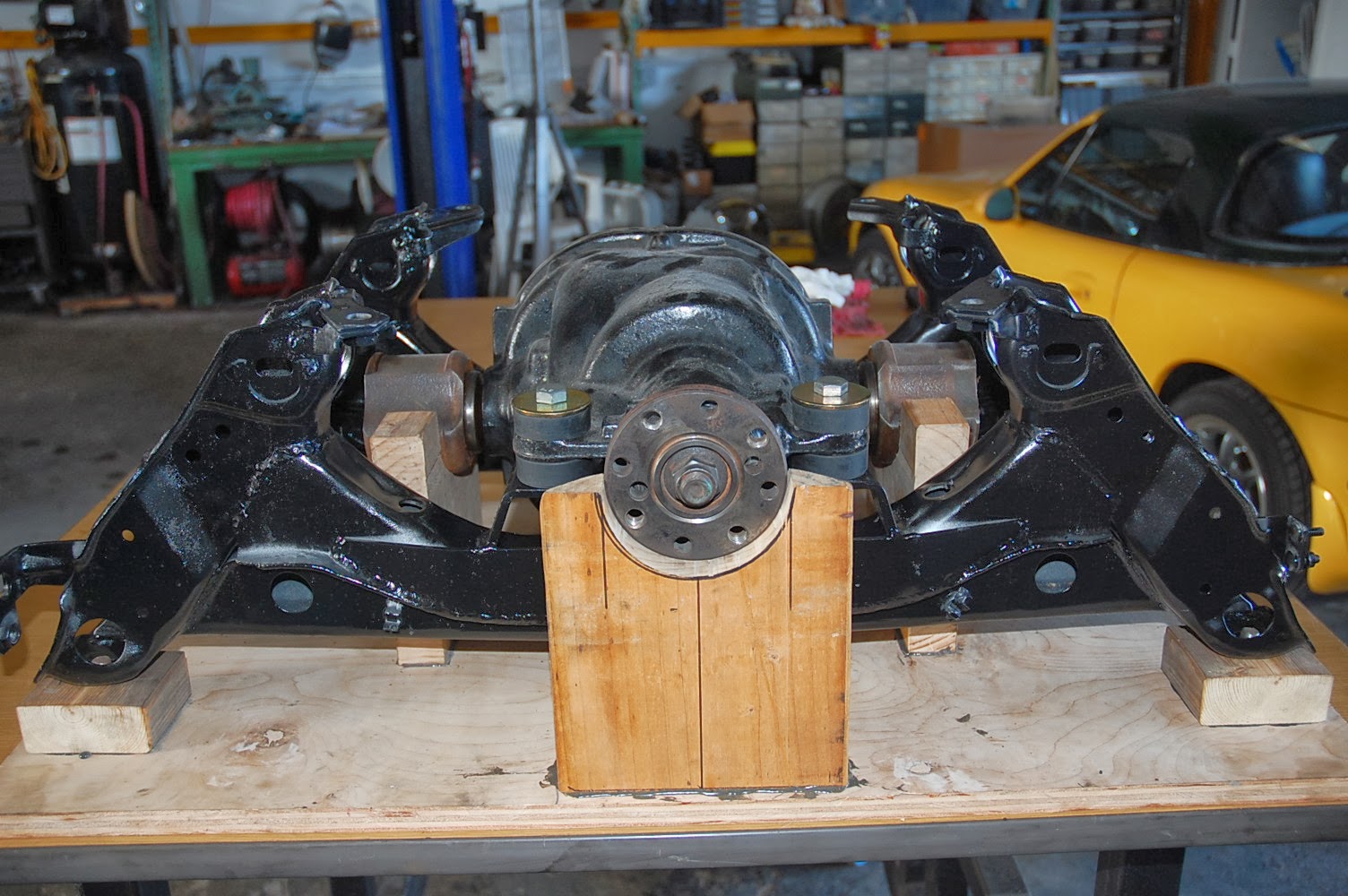


The following pics are of the latest as of 1-26-2014 version using the 3" X 5" extruded angle rather than the bent 1/4" plate for the rear mounts. I wanted the thicker material to minimize the mods to the rubber mounts and their spacer, plus I think it looks better.


The chamfer on the corners seemed like a good idea, but they proved to be unnecessary as you can see in the pics of the welded in plate


The bolts thru the cover casting mounting ear are metric, the bolts into the plate are 1/2-18 to mate to the
1/ 2-18 lug nuts that I used as weld nuts on the back side of the plate. The subframe crossmember has large clearance holes for the nuts.
You can see that the chamfers on the corners of the plate are unnecessary and in fact if the plate had corners, the weld would be continuous at the gussets.


This pic is of a previous build, I neglected to take a shot of the finished frame with the long gusset across the pedestals.
EDIT 11-02-2021 I think it needs to be emphasized that these gussets across the front and rear portions of the subframe are very necessary. Recent instances of 8.8 converted subframe failures have been published on the internet; in some cases, the mounting scheme uses some of the ideas found here, but it doesn't appear that any attention was given to adding the gussets.


Under the "AX" on the door jam sticker:
Edit 11-4-2022. Some pics of the mounting scheme I chose for the Explorer 8.8. It appears to be a more robust version of the 8.8 case and fits really well into the Miata subframe.
Not much detail in these pics but if there's any interest I can add some more. Basically 2 big steel tubing bushings in the rear, urethane mounting bushings and long thru bolts into the stock mounting holes on the rear cover. I used the stock rubber mount on the front, similar to the front mount of the early T-Bird style 8.8.
I added quite a bit of 1/8 steel plating over and around the steel tubes, as they required a fairly large section of the subframe structure to be cut out, and I wanted to transfer the stresses to the outer extremities of the subframe, closer to where the subframe mounts to the unibody "frame".
Also, the earlier version of this rear uses the single front mount as shown, the later ones use a double mount similar to the earlier T-Bird case. I'm not sure why the world of automotive engineers thinks its OK to use 3 mounting points instead of 4, but I see this 3 point design in other applications like the Getrag and BMW.


PNG files of the fabricated pieces involved in the conversion. Open in new tab.


Link to a handy list of door codes for identifying the rear end installed at the factory for Tbirds and Cougars. Probably good for just about any Ford, actually.
http://www.tccoa.com/articles/gears/gears.html
The important info:
Under the "AX" on the door jam sticker:
| Conventional | Lock | Rear Axle Ratio |
|---|---|---|
| G | H | 2.26 |
| B | C | 2.47 |
| 8 | M | 2.73 |
| 7 | - | 3.07 |
| Y | Z | 3.08 |
| 4 | D | 3.42 |
| F | R | 3.45 |
| 5(W5) | E(XE) | 3.27 |
| 6 | W | 3.73 |
| 2 | K | 3.55 |
| A | - | 3.63 |
| J | - | 3.85 |


